Background
In 2025, Americans are expected to spend a total of $1.47 Trillion dollars through online retail, a staggering 9.78% increase from the year prior [1]. In 2024, 18.4% of retail sales were completed online, requiring retailers to ship products from fulfillment centers directly to consumers with an ever-increasing desire for speed and accuracy. As result, online retailers are turning their sights to automated methods, leveraging Automated Mobile Robots (AMR) and areal drones. While great success has been achieved in the deployment of these technologies, they have primarily been managed as isolated deployments; controlling only one type of robot at a time. Systems such as Amazon Robotics ground-only approach introduces congestion on the warehouse floor and leaves volumetric space unused. The Collaborative Autonomous Robotics Platform (CARP) aims to orchestrate varying robotic modalities within a shared, physical operating environment. Because each robot variant can have drastically different capabilities, the system operates at both the micro and macro level. Upon receiving a request for a product, CARP identifies the optimum strategy to complete the task using the best combination of robots and existing infrastructure for the job. This combination of system types enables highly efficient space utilization. For example, a ground-based robot can collect heavy objects stored near ground level, meanwhile, a drone is flying above collecting lightweight merchandise. Built-in optimization algorithms consolidate merchandise for longer distance travel, freeing robots to accomplish nearby tasks and reducing energy and maintenance costs.
This system innovates upon three key aspects:
- Decentralization - In the event of a partial connectivity loss or a failure of a particular type of robot the remainder of the system can continue to operate independently.
- Task Assignment Optimizatio - When assigning tasks, morphologic constraints and telemetry are considered, such as payload capacity, reachability, and respective battery levels.
- Human and Robot Coexistence - Robots speed, routes, and airspace are dynamically adjusted when humans enter designated areas. Ensuing workers and robots can safely work together.
- Integration with Existing Infrastructure - warehouse infrastructure, such as elevators, conveyors, and door I/O systems, enabling seamless vertical and horizontal mobility for robots
Use Cases
John
John orders a new computer monitor online and chooses next-day shipping at checkout. Upon placing the order, the e-commerce site's database sends an order to the fulfillment center closest to John, that has the product in stock. This fulfillment center contains a large warehouse floor with 30-foot-tall storage shelves. There is a basement level that is accessible by a large elevator capable of carry heavy loads and is where maintenance department resides. At one end of the warehouse there is a smaller building attached where the shipping department resides. Here, products are packed into boxes and loaded onto trucks. Connecting the shipping department to the warehouse is a conveyer belt that runs down the middle of storage facility center but terminates at the center of the warehouse. Currently, warehouse workers are randomly assigned orders to fulfill and can view them on their tablets. They then utilize order pickers, forklift style machines that lift the workers to the desired shelf so they can manually retrieve the product. Once the items are collected, they are placed in a bin and placed on the conveyer belt. The order bin is then received by the shipping department and placed into a cardboard box by a worker. This box is then placed on another conveyer belt to put on the correct to be sent to the shipping company. At the end of the warehouse workers' shift, they drive the picker onto the elevator to bring it to the maintenance department for charging and any needed repairs.
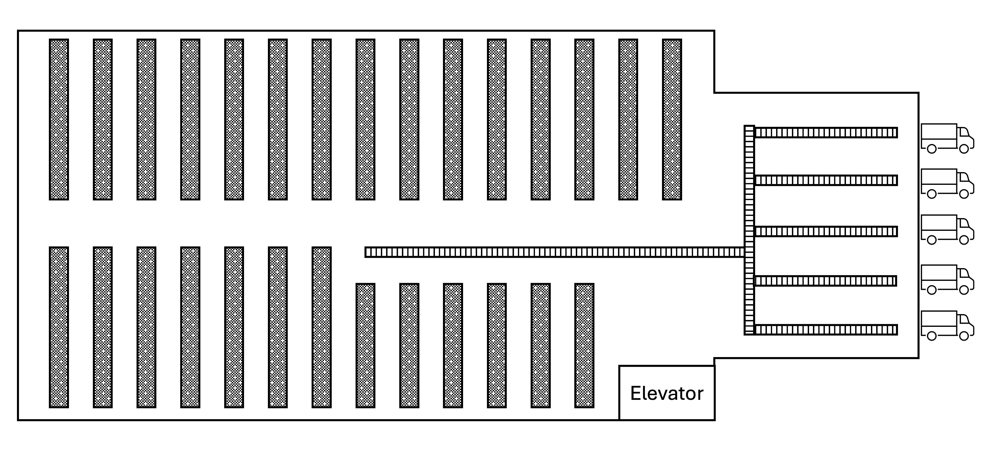 Figure 1. Illustration of the warehouse layout.
Byte Bay
Byte Bay is a large online electronics retailer that sells computers, TVs, phones, gaming systems and more. Leading up to the holiday season, the retailer experiences a drastic increase in sales, which requires an increase in staffing and strains their existing warehouse management systems. The primary fulfillment center is a centrally located, high throughput campus consisting of multiple warehouse buildings. These buildings vary in size, configuration, and automation level, but all contain densely packed racks, which also vary in height. The campus consists of a preexisting network of conveyer belts, forklifts, some automated robots, and warehouse systems. Because new warehouse buildings were constructed at different times, the age and sophistication vary at each warehouse. For example, the newest warehouse has state-of-the art robotic pickers that deliver products directly to the shipping facility via drone or ground robot. Meanwhile, the oldest facility relies on pickers walking and driving order-pickers and club-carts. Naturally, this has resulted in some inefficiencies like misplaced items as a result some warehouses utilize drones to help with inventory management and locating missing items. This retrofit was shown to be a cheaper alternative than refreshing the entire warehouse while keeping jobs in the community. Some buildings are interconnected by tunnels and/or conveyor belts, however, there isn't much consistency. Unfortunately, each system operates independently from one another, and the manufacture varies as well. This results in the facility operating as several co-located fulfillment centers instead of one harmonious fulfilment campus. This can often result in orders being delayed or multiple items placed in one order being shipped separately; raising shipping costs, increasing carbon emissions and leaving consumers to track multiple packages.Requirements
Primary Customer
Operators of high-volume, multi-building fulfillment campuses. Facilities with dense racking, multi-level mezzanines, large conveyor systems, and nonstop inbound/outbound waves who must squeeze more throughput from the same footprint while keeping people safe. These sites run thousands of picks per hour across fast-moving SKUs, face sharp demand spikes during promotions and peak seasons, and field mixed fleets: lightweight aerial drones for rapid scanning and tote retrieval, and AMRs for heavier floor transport. Today, aisle congestion, elevator queues, and ad-hoc human interventions routinely stall flow, and legacy fleet managers treat each robot type in isolation, leaving capacity stranded. These operators need a coordination layer that understands both airspace and floor traffic, allocates tasks with battery and capability awareness, arbitrates shared resources like crossings and loading bays, and reacts instantly when associates enter safety zones; all without ripping and replacing existing conveyors, doors, or WMS integrations. By unifying planning and safety across modalities, they can hit aggressive SLA targets, cut deadheading and idle time, and scale reliably from a single building to a regional hub.
Intended Users
- Control room supervisors
- Floor associates
- Maintenance/IT
- Robotics engineers/partners
Out-of-Scope Work
This is a software-only initiative. We are not designing or procuring physical robots, airframes, AMR chassis, batteries, chargers, sensors, docking stations, or safety hardware, nor are we responsible for facility modifications such as networking, power, racking changes, or signage required to operate them. We do not assume ownership of the customer’s WMS/ERP or related master data governance, nor will we replace, replatform, or manage those systems beyond integrating through agreed interfaces. Full regulatory certification, compliance audits, and safety validation of specific robot models or facility configurations are outside scope. We will provide interface specifications, logs, and guidance to support the customer’s certification efforts. Also excluded are ongoing operations, on-site commissioning, preventive maintenance, and operator training beyond initial handoff materials. Any third-party licensing, infrastructure hosting, or SLAs for underlying networks and cloud services are the customer’s responsibility, with our deliverables limited to the CARP software, its APIs, and documentation.
Assumptions
The site provides reliable Wi-Fi or private network with quality-of-service guarantees suitable for low-latency control traffic. Fixed infrastructure such elevators, doors, and conveyors has wired backhaul for deterministic I/O and telemetry. Network segmentation and coverage planning are handled by the customer.
Each robot implements certified stop/land/loiter behaviors that can be invoked autonomously or via external command. CARP can trigger these behaviors through documented interfaces, but it does not replace the robots’ native safety controllers. Vendors must furnish evidence that these behaviors function independently of cloud connectivity.
Drones operate strictly within approved indoor volumes defined in the digital twin. Ceilings are geofenced, and transient “no-fly” zones can be activated for maintenance or human activity. Any operation outside these bounds is considered a policy violation and is blocked by CARP.
All third-party systems such as WMS, conveyor PLCs, elevator controllers, door I/O, and identity providers expose stable, versioned APIs or electrical I/O for control and feedback. Partners commit to change windows and deprecation schedules so CARP can maintain compatibility. Where only I/O is available, signal timing and protocols are documented and validated during integration.
High-level requirements (HLRs)
HLR-0.1 Provide a live, unified map of floor and airspace including aisles, shelves, human zones, and restricted “no-fly” volumes with sub-second updates.
HLR-02. Coordinate drones and AMRs for joint missions such as drone fetch to mezzanine, drone handoff to AMR.
HLR-03. Assign tasks based on capability, location, SoC, and duty cycles.
HLR-04. Dynamically slow/redirect/hold robots when humans enter safety zones; allow human overrides with audit trail.
HLR-05. Integrate with elevators, conveyors, doors/I/O to schedule shared resources and vertical moves.
HLR-06. Optimize for order-level SLAs and global flow, not individual robot utilization.
HLR-07. Degrade gracefully on comms loss; safe stopping/loiter behaviors.
HLR-08. Support common fleet/robot APIs and warehouse data systems.
Functional requirements (FR)
Task intake and orchestration
FR-001. Ingest tasks from WMS/host via API/queue; de-duplicate and prioritize by SLA and policy.
FR-002. Support pick, putaway, cycle count, inventory scan, cross-dock, inspection, and ad-hoc assist.
FR-003. Create multi-leg missions spanning drone and AMR with explicit handoff points.
FR-004. Enforce prerequisites and completion checks.
Allocation and scheduling
FR-010. Assign only to robots with required payload, reach, gripper/sensor, or flight clearance.
FR-011. Include SoC, cycle age, and projected mission energy in utility function.
FR-012. Penalize cross-warehouse deadheading in scoring.
FR-013. Re-assign mid-mission if incidents or better options arise; ensure safe handover.
Routing and deconfliction
FR-020. Compute time-expanded paths in 2D (floor) and 3D (air) with clearance envelopes.
FR-021. Enforce dynamic “no-fly/ no-drive” zones for manual, sensor, or policy-triggering.
FR-022. Reserve/lock aisle crossings, elevator cars, conveyors, and loading bays with time-window tokens.
FR-023. Apply cross-modal right-of-way rules such as emergency drone descent yields to human zone.
FR-024. Onboard collision avoidance complements global plan; report deviations.
Human-in-the-loop safety
FR-030. Create caution/slow/stop zones with different behaviors for drone vs AMR.
FR-031. Consume inputs from vision, badges, LIDAR, BLE to detect human presence.
FR-032. Apply speed caps/hold states within milliseconds of detection.
FR-033. Supervisors can freeze/resume individual robots, zones, or whole site with reason logging.
FR-034. Capture who/when/why for every override and outcome.
Energy and maintenance
FR-040. Schedule opportunistic charges/swaps; avoid peak resource contention.
FR-041. Track temps, vibration, battery health, motor currents; raise alerts on thresholds.
FR-042. Create maintenance tickets upon anomaly patterns.
Infrastructure integration
FR-050. Call cars, select floors, ensure door interlocks; confirm capacity/weight.
FR-051. Trigger automatic doors, beacons, and warning lights tied to reservations.
FR-052. Synchronize merge timings and tote handoffs; confirm barcode/weight accept.
Data, maps and localization
FR-060. Maintain warehouse digital twin: static (shelves) + dynamic layers (obstacles/zones).
FR-061. Provide NTP/PTP time sync reference for fleet.
FR-062. Fuse UWB/VIO/LIDAR/IMU/GNSS (if any) for per-robot pose with covariance.
FR-063. Version maps; support scheduled reconfiguration windows.
Interfaces and UX
FR-070. Web UI with live map, alarms, KPIs, drill-downs, playback.
FR-071. Northbound REST/gRPC + event bus; southbound robot adapters.
FR-072. Incident/SLA alerts to Slack/Email/SMS per policy.
FR-073. Simulate plans against recorded traffic before go-live.
KPIs and reporting
FR-080. Orders/hour, lines/hour, mission latency, resource utilization, zone downtime.
FR-081. Near-miss counts, override frequency, zone entries, MTBF/MTTR.
FR-082. kWh/mission, charge queue times, battery aging.
Security and governance
FR-090. Roles for Associate, Supervisor, Engineer, Admin; least-privilege defaults.
FR-091. Immutable logs for commands, config, and data access.
FR-092. Rotate robot credentials; certificate-based mutual auth.
Critical non-functional requirements (NFR)
Performance and scale
NFR-001. New task → assignment decision ≤500 ms p95 under 200 concurrent tasks.
NFR-002. Path replan after obstruction ≤300 ms p95; local avoidance reaction ≤50 ms on-robot.
NFR-003. Zone changes propagate to all active planners ≤200 ms p95.
NFR-004. Support up to 300 AMRs + 150 drones per site; 10 sites per control plane.
Safety and reliability
NFR-010. Control plane ≥99.95% monthly; on-robot safety behaviors independent of cloud.
NFR-011. Loss of comms: AMR safe stop within < 1 s; drone loiter/land in < 2 s per policy.
NFR-012. Maintain minimum separation: floor ≥0.5 m, air ≥1.5 m unless docked/hand-off.
NFR-013. Fleet clocks synchronized to ≤1 ms p99 to support reservation windows.
NFR-014. Pose error ≤10 cm floor p95; ≤20 cm air p95 in mapped zones.
Security and privacy
NFR-020. TLS 1.3 in transit; AES-256 at rest; FIPS-compliant options for regulated sites.
NFR-021. MFA for privileged roles; service-to-service mTLS; per-robot identity.
NFR-022. Store only operational telemetry; redact PII from video/vision payloads.
Interoperability & extensibility
NFR-030. ROS2 Foxy/Humble compatible; OpenAPI-described northbound APIs; OPC-UA adapter for industrial I/O.
NFR-031. New robot vendor adapter deliverable in ≤4 weeks with provided SDK scaffold.
NFR-032. Backward-compatible event schemas for 12 months.
Operability & maintainability
NFR-040. Metrics, logs, and traces exposed via OpenTelemetry; 30-day hot retention.
NFR-041. Zero-downtime rolling controller updates; robot firmware staged with blue/green and canary cohorts.
NFR-042. All zones/policies map-versioned and Git-tracked.
Compliance and environment
NFR-050. OSHA-aligned floor safety policies; facility-specific airspace policies documented and enforced.
NFR-051. Audible/visual cues meet facility standards; night-shift safe-lighting modes.
NFR-052. Average mission energy consumption reduced ≥10% vs. baseline single-modality operations in pilot.
High-Level Design
The CARP system is designed as a unified "air traffic control" layer for high-volume fulfillment campuses. Its architecture is built upon a microservices, event-driven platform (HLR-08), prioritizing safety (HLR-04), fault tolerance (NFR-010), and real-time performance (NFR-001).
1. CARP Component Breakdown and Responsibilities
The CARP system consists of nine primary, highly cohesive microservices, each identified by a unique, traceable ID (CARP-M for Module). Defining these components first establishes the vocabulary used throughout the design.
CARP-M0: Apache Kafka Event Bus (The Data Backbone)
Central message queue for asynchronous communication, buffering, and real-time data flow between all components. High-priority topics ensure critical commands (like safety stops) are processed instantly (NFR-003).
CARP-M1: Digital Twin Service (Source of Truth)
Maintains the authoritative, live, unified 3D map of the warehouse (HLR-0.1, FR-060). It fuses robot position data (FR-062), tracks dynamic obstacles and human zones, and serves as the global state repository for all planning and safety modules.
CARP-M2: Mission Orchestration Service
Manages the end-to-end lifecycle of a work order. It ingests tasks (FR-001), prioritizes them by SLA (HLR-06), and breaks them into complex, multi-leg missions spanning drone and AMR activity (HLR-02, FR-003) with explicit handoff points.
CARP-M3: Fleet Scheduling Service (MRTA)
The core task allocation engine (HLR-03). It uses a utility scoring function to evaluate the optimal robot or team for a mission leg, considering capability (FR-010), location, State of Charge (SoC), projected mission energy (FR-011), and penalty for unnecessary travel (FR-012). It can safely reassign tasks mid-mission (FR-013).
CARP-M4: Traffic Control & Planning Service
Manages 3D path planning and global deconfliction (HLR-01, HLR-05). It computes time-expanded, collision-free paths (FR-020) for all robots, rapidly replanning routes (NFR-002) when dynamic zones are triggered. It manages the reservation system (time-window tokens) for shared resources like aisle crossings and elevators (FR-022).
CARP-M5: Safety Management Service
The critical safety enforcement module (HLR-04). It consumes real-time human presence data (FR-031), enforces zone-specific robot behaviors (FR-030), and issues preemptive speed caps/hold commands within milliseconds (FR-032). It manages all authenticated supervisor overrides (FR-033), creating an immutable audit log (FR-034, NFR-091).
CARP-M6: Infrastructure Integration Service
The adapter layer for fixed facility assets (HLR-05). It integrates with proprietary APIs/I/O of elevators, conveyors, and automatic doors (FR-050). It handles the complex scheduling handshake with CARP-M4, ensuring tight synchronization and safety interlocks during resource use (FR-052).
CARP-M7: Robot Adapter Layer (Execution Control)
The Southbound layer translating CARP's generic commands into vendor-specific instructions (HLR-08, NFR-030). It publishes raw robot telemetry (pose, battery health) and enforces core safe stop/loiter behaviors that function independently of cloud connectivity (HLR-07, NFR-011). It is designed to be highly extensible (NFR-031).
CARP-M8: API Gateway and Web UI (Northbound Interface)
The system entry point. The API Gateway enforces strong authentication (MFA, mTLS) and authorization (FR-090). The Web UI (FR-070) provides the live map, KPI dashboard (FR-080), alarm feed (FR-072), and supervisor controls.
CARP-M9: Observability & Telemetry Service
Handles analytics, metrics, and maintenance. It calculates real-time KPIs (FR-080, FR-081), monitors asset health (FR-041), and schedules opportunistic charging/maintenance (FR-040, FR-042). It exposes metrics via OpenTelemetry (NFR-040) and manages policy-based alerting.
2. Top-Level Architecture: The Event-Driven Microservices Platform
The CARP system is structured around the defined components, emphasizing scalability (NFR-004), high availability, and rolling updates (NFR-041).
Architectural View
The system architecture is a clear Hub-and-Spoke model. CARP-M0 (Kafka) acts as the central Hub, through which all microservices communicate. External systems connect via CARP-M8 (API Gateway) for input/output and CARP-M7/M6 (Adapters) for low-level control. This model ensures loose coupling and high performance.
Key Architectural Layers
This breakdown shows how the CARP components map to the functional layers of the overall system.
| Layer | Responsibility | Components Involved |
|---|---|---|
| 1. External Integrations | Data ingestion and final command execution. | WMS/ERP, Robots (AMR/Drone), Facility Infrastructure. |
| 2. Northbound Interface | User access, external API exposure, and task intake. | CARP-M8 (API Gateway & Web UI). |
| 3. Core Logic Plane | Real-time decision-making, planning, and safety enforcement. | CARP-M1 (Digital Twin), CARP-M2 (Orchestration), CARP-M3 (Scheduling), CARP-M4 (Planning), CARP-M5 (Safety). |
| 4. Data Backbone | Asynchronous, decoupled, immutable data flow (FR-091). | CARP-M0 (Apache Kafka Event Bus). |
| 5. Southbound Interface | Robot and infrastructure specific protocol translation. | CARP-M7 (Robot Adapter Layer), CARP-M6 (Infrastructure). |
| 6. Persistence | State storage, logging, and metrics retention. | Time-Series DB, Immutable Audit Logs, Map/Config Store (supported by CARP-M9). |
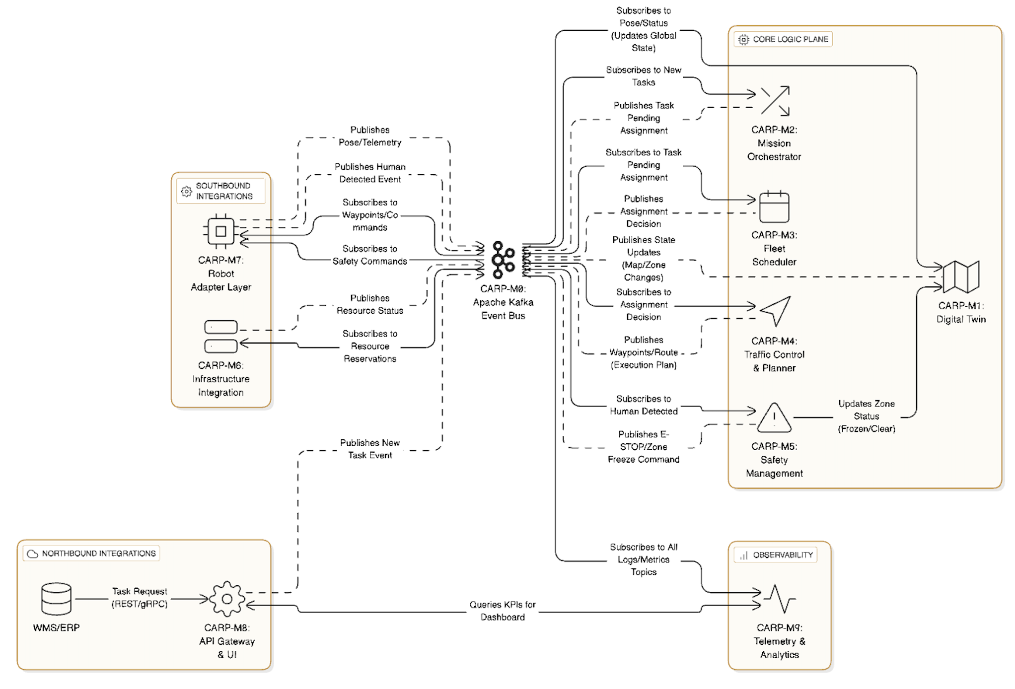 Figure 1. High Level Design UML
3. System Execution Flow: CARP in Action
The overall design works as a continuous loop of command, execution, and feedback, centered around the event bus (CARP-M0).
A. Task Lifecycle: From WMS to Robot Command
- Ingestion & Orchestration (CARP-M2): The WMS sends a "Pick Task" request to CARP-M8 (API Gateway). CARP-M2 consumes this event from CARP-M0, validates it (FR-001), and determines it requires a drone to fetch and an AMR for transport (HLR-02). It creates a multi-leg Mission ID.
- Scheduling (CARP-M3): CARP-M2 publishes a "Drone Leg Pending Assignment" event. CARP-M3 consumes this, checks robot status (location, SoC, capability) from the CARP-M1 Digital Twin, and selects the optimal drone (HLR-03). It publishes an "Assignment" event (NFR-001).
- Path Planning (CARP-M4): The Drone Adapter (CARP-M7) and CARP-M4 consume the assignment. CARP-M4 computes a 3D path, reserves the necessary airspace, and schedules the delivery to the handoff point. If a vertical move is needed, it coordinates with CARP-M6 (Infrastructure) to reserve an elevator car (HLR-05).
- Execution (CARP-M7): CARP-M4 streams path waypoints to the drone's specific adapter in CARP-M7, which translates and forwards the commands to the drone. The drone executes the mission, continuously sending pose telemetry back to CARP-M1.
- Completion & Handoff: Once the drone reaches the handoff point, CARP-M2 validates completion (FR-004) and triggers the assignment process for the AMR transport leg.
B. Real-time Safety Intervention
- Detection (External/CARP-M7): A LIDAR sensor detects a human entering Aisle 3 (a defined Stop Zone) and publishes a "Human Presence Detected" event onto CARP-M0 (FR-031).
- Immediate Enforcement (CARP-M5): The Safety Management Service (CARP-M5) consumes this high-priority event. Within milliseconds (NFR-003, FR-032), it identifies the affected robots in that zone (via CARP-M1) and immediately publishes "EMERGENCY STOP" commands to their respective adapters in CARP-M7.
- Execution & Audit (CARP-M7 & M9): The robot adapter (CARP-M7) ensures the drone loiters and the AMR stops (HLR-07). Simultaneously, CARP-M9 logs the incident, and CARP-M5 marks the Aisle 3 zone in the Digital Twin (CARP-M1) as "FROZEN."
- Rerouting (CARP-M4): CARP-M4 receives the "Zone Frozen" update from CARP-M1 and recalculates paths for all approaching robots (NFR-002), diverting traffic until CARP-M5 removes the freeze (HLR-04).
4. Traceability Matrix: HLRs to Design Components
| HLR ID | Requirement Summary | Primary Responsible CARP Component(s) |
|---|---|---|
| HLR-0.1 | Live, unified map of floor and airspace. | CARP-M1 (Digital Twin), CARP-M7 (Adapter Layer), CARP-M8 (Web UI) |
| HLR-02 | Coordinate joint missions (drone fetch/handoff to AMR). | CARP-M2 (Orchestration), CARP-M3 (Scheduling) |
| HLR-03 | Assign tasks based on capability, location, SoC. | CARP-M3 (Scheduling), CARP-M1 (Digital Twin) |
| HLR-04 | Dynamically slow/redirect/hold on human entry; allow human overrides. | CARP-M5 (Safety Management), CARP-M7 (Adapter Layer) |
| HLR-05 | Integrate with shared resources (elevators, conveyors). | CARP-M6 (Infrastructure Integration), CARP-M4 (Traffic Control) |
| HLR-06 | Optimize for order-level SLAs and global flow. | CARP-M3 (Scheduling), CARP-M2 (Orchestration) |
| HLR-07 | Degrade gracefully on comms loss; safe stopping/loiter behaviors. | CARP-M7 (Adapter Layer), CARP-M5 (Safety Management) |
| HLR-08 | Support common fleet/robot APIs and warehouse data systems. | CARP-M8 (API Gateway), CARP-M7 (Adapter Layer) |
Design Rationale
The CARP system is architected as a microservices-based, event-driven platform deployed on Kubernetes for scalability. This design emphasizes safety above all, followed by protection of equipment/inventory, then fault tolerance, and finally performance. By using Apache Kafka as the data backbone, CARP decouples components and ensures real-time communication through events. This allows the system to react to changes such as new tasks, robot status, and human presence instantly and reliably. In the event of any failure or anomaly, the system defaults to safe behavior. For example, communication loss triggers robot halt reflecting the core principle that safety actions always take precedence over productivity.
CARP's architecture is organized into functional modules, each responsible for a subset of the requirements. These modules communicate primarily via Kafka event streams and use well-defined APIs where necessary. Kubernetes provides an orchestration layer to deploy these services with auto-scaling, rolling updates, and high availability. The sections below break down the design by module/function, discussing how each meets the requirements and the design decisions made with alternatives considerations. In all modules, design choices were guided by the priority: personnel safety, asset safety, fault tolerance, and performance.
Task Ingestion and Orchestration Modules
This module handles task intake and mission orchestration, covering HLR-01, HLR-02 and FR-001 to FR-004. It ingests work orders such as pick or putaway tasks from external systems (WMS/ERP) and orchestrates multi-robot missions.
Through a northbound API (FR-070/FR-071), the system receives task requests via REST or message queue. Tasks are deduplicated and prioritized by SLA (FR-001) and then broken into multi-leg missions if needed (FR-003). For example, a mission might require a drone to retrieve an item from a mezzanine and hand it off to an AMR on the floor. The orchestrator will split this into a drone sub-task and an AMR sub-task, with a defined handoff point (FR-002, FR-003). The orchestrator also enforces prerequisites and completion checks for each stage (FR-004).
We opted for a hybrid approach centered on a Task Orchestration Service that uses event-driven communication. The orchestrator is a microservice on Kubernetes that subscribes to incoming task events from the WMS interface and orchestrates mission steps by publishing command events. It maintains mission state which can be stored in a lightweight state store or in memory with periodic checkpoints to Kafka. This design ensures that complex multi-robot workflows are managed explicitly for correctness and safety. For instance, the orchestrator will not dispatch a drone and an AMR into the same physical space without timing and handoff coordination, preventing collisions or idle waits (HLR-02, FR-003). We prioritized this controlled sequence to ensure human safety and asset protection. The orchestrator can hold or adjust missions immediately if any safety event occurs (HLR-04).
By using Kafka, the task intake is decoupled. The system can buffer bursts of task events without losing data. Multiple instances of the Task Orchestration Service can run in a consumer group to process different tasks in parallel, scaling out as needed. Kubernetes Horizontal Pod Autoscaler (HPA) can spin up more instances on high load. Each mission can be given a unique ID and all events related to that mission carry this ID, enabling any service to reconstruct the sequence if needed. This design meets NFR-001, as task assignment decisions in collaboration with the scheduling module happen within a few hundred milliseconds. Kafka adds minimal latency and the orchestrator's logic is optimized for quick decisions. Overall, this module ensures that tasks are efficiently taken in and broken down, while always ready to pause or cancel missions if safety dictates.
Robot Allocation and Scheduling Modules
This module decides which robot(s) should carry out a given task, fulfilling HLR-03 and FR-010 to FR-013. It ensures that each task is assigned to an optimal robot or team of robots considering capabilities, location, and battery, and can reassign on the fly if conditions change.
When a new task or mission step is created by the orchestrator module, the Scheduling Service evaluates the available drones and AMRs. It considers capability constraints (FR-010), current location and proximity to the task, State of Charge (SoC) and battery levels (FR-011), and even recent duty cycles to avoid overuse. The scheduler uses a utility scoring function (per FR-011) that also penalizes unnecessary travel (FR-012) to maximize efficiency. For joint missions (HLR-02), it will allocate a pair or team, choose a drone and an AMR that together minimize total fulfillment time. The scheduler must also handle dynamic reassignments (FR-013); if a robot fails or a higher-priority task preempts, it can reallocate a task mid-mission safely.
The scheduling problem here is essentially a multi-robot task allocation (MRTA). We implemented a Centralized Fleet Scheduler microservice. The orchestrator publishes a “task pending assignment” event, and the scheduler service consumes it. The scheduler maintains an up-to-date view of each robot's status, which it gets from the Digital Twin and Robot Interface modules via events. Using this data, it computes the best assignment. For example, picking the nearest available drone that has enough battery and appropriate payload capacity for a pick task. If the task is multi-leg, it pairs a drone and AMR considering their combined route (drone fetch then meet AMR at a handoff point). The decision is then emitted as an “assignment” event, which the orchestrator and relevant execution modules receive.
To meet fault tolerance and speed requirements, this service is stateless. It derives all needed info from incoming events and the shared world state. We run it with at least two instances for redundancy; if one fails mid-computation, the task event is simply reprocessed by another instance leveraging Kafka consumer group rebalance. The scheduling algorithm is optimized for <500ms decisions (NFR-001). We use heuristics and only do heavy computations like path estimation if needed. Because this module directly affects efficiency and asset usage, we ensure it never sacrifices safety. For example, it will not assign a nearly depleted drone just because it's closest due to a battery safety rule, and it will avoid assignments that send too many robots into one area at once; thus preventing congestion and reducing risk of collisions. If a robot reports an incident or failure mid-mission (FR-013), the scheduler can immediately produce a re-allocation event to dispatch a second drone to take over a delivery, while the orchestrator coordinates a safe handover. This module thus satisfies HLR-03 and contributes to HLR-06 optimizing global flow, while obeying safety and fault tolerance priorities.
Path Planning and Deconfliction Modules
This module handles navigation planning for both aerial and ground robots, ensuring they don't collide and efficiently share resources (HLR-01, HLR-05). It covers FR-020 to FR-024 and FR-050 to FR-052. Essentially, once tasks are assigned to robots, this component charts the time-space paths for each robot and manages intersections to avoid conflict.
The Path Planning & Traffic Control Service computes feasible routes for drones in 3D airspace and AMRs on 2D floor paths that respect all constraints. Path planning and traffic management is a complex, continuous problem. We implemented a Central Traffic Control Service using a global planning approach. The Digital Twin acts similarly to a blackboard. When the Scheduling module assigns a task to a robot, it triggers a route planning event. The Path Planning service then computes an optimal route for that robot from its current position to the goal, considering current and predicted positions of other robots and reserved resources. We use algorithms for pathfinding in static space combined with a time dimension, ensuring no two robots are scheduled in the same space at the same time.
After computing a route, the planner publishes the route or waypoints to the robot via Kafka. It simultaneously marks the path's space-time segments as reserved in the Digital Twin's model, so any subsequent planning for other robots will avoid those segments (FR-022). For shared resources like elevators, the planner will coordinate with the Infrastructure Module to request an elevator at a certain time. The infrastructure service responds via event when the elevator is ready, at which point the planner finalizes that segment of the route and signals the robot to proceed (FR-050, FR-051). This handshake ensures tight coupling for critical handoffs without blocking the whole system. The use of events allows other planning to continue in parallel.
To handle dynamic changes, the planning service subscribes to events like “obstacle detected in aisle 3” or “human entered zone A”. On such an event, it will mark that area as temporarily closed (FR-021) and recompute any affected active routes (NFR-002). New routes or hold commands are then sent out to robots within ~200-300ms, fulfilling the NFR-002 replan requirement. We also leverage the on-robot local avoidance capabilities (FR-024) each robot has basic collision sensors native to their platform to stop or swerve around sudden obstacles. Our architecture supports this by not micromanaging every millisecond of motion. If a robot performs a minor avoidance maneuver, it will report it as an event, and the planner can adjust the global plan if needed. This layered safety ensures that even if the global planner's last update was a fraction of a second ago, the robot itself can react in between (NFR-002).
In terms of performance and scaling, we deploy the Path Planning service as a set of identical instances on Kubernetes. The Kafka event queue allows multiple planners to work concurrently on different route requests. We partition planning tasks by zone or by robot fleet to avoid two instances solving conflicting plans simultaneously. Because this function is computationally heavier, we allocate more resources to it and allow Kubernetes to scale it out under load. The 300 robots per site (NFR-004) are handled by efficient planning algorithms and offloading less critical computations to background processes. The design prioritizes safety. If ever in conflict, the planner will choose a slower/longer route or even hold a robot idle rather than risk a close call. Efficiency is important (HLR-06), but never at the cost of violating separation or rushing a resource handoff. This careful, centralized coordination meets HLR-05 and HLR-01 by effectively acting as the “air traffic control” of the warehouse.
Human Safety and Zone Management Modules
This module monitors human presence and manual interventions, enforcing human-in-the-loop safety (HLR-04) and covering FR-030 to FR-034. It ensures robots slow down, stop, or reroute when humans are in proximity, and allows authorized humans to pause or override robot operations with proper logging. Safety Management Service has two primary roles automated zone enforcement and manual override and intervention.
The warehouse is instrumented with sensors that feed into CARP whenever a human or any other unexpected entity enters a protected area (FR-031). These areas can be defined as caution zones. In caution zones, robots may continue but at reduced speed. In stop zones no robot motion allowed per FR-030. The service consumes these sensor events and correlates them with map zones. Within milliseconds of detecting a human in a danger zone, CARP must respond (FR-032). The Safety service will publish commands to all robots in that zone or approaching it to either slow down, pause, or take an alternate route. Drones may be commanded to hold position or ascend to a safe hover altitude; AMRs may decelerate to a crawl or stop completely. These commands are high priority and bypass normal scheduling queues if needed.
Manual override and intervention occurs through the UI or physical controls; supervisors can issue overrides (FR-033). They might invoke an e-stop on a specific robot, freeze all movements in a zone for an emergency, or resume operations when clear. Each such action is authenticated (FR-090, NFR-021) and logged with timestamp and reason (FR-034, NFR-091). The Safety module ensures that any manual stop command has immediate effect system-wide.
Safety enforcement is essentially a real-time control loop overlay on the whole system. CARP's safety module is implemented as a combination of real-time event processing and redundant fail-safes. The Safety Management Service runs as one or more instances on Kubernetes, each capable of handling a subset of sensors or zones for scalability. It uses a rules engine or state machine for zone policies (FR-030). For example, if a human is detected in a caution zone, the rule might be “allow AMRs to continue but at 50% speed and no drones below 5m altitude in that zone.” These rules can be configured per site or zone. The service subscribes to all human-detection events (FR-031) and zone status changes, and it references the Digital Twin to map those coordinates to zone IDs. Then it issues speed change or stop commands to the affected robots through the Robot Interface. The latency from detection to command is kept very low (HLR-04). Kafka and our network assumptions support this, but we also deploy this service close to the edge to minimize round-trip time.
For manual interventions (FR-033), the system provides a UI button and also integrates physical E-stop buttons via the Infrastructure module if required. For example, when a supervisor clicks “Freeze Zone A,” the Safety service broadcasts a ZoneA_Freeze event. Robot controllers subscribed to zone commands will execute an immediate stop, and the orchestrator will mark missions in that zone as on hold. All such interventions create log events which the safety service tags with user ID, reason code, and affected robots (FR-034). These logs go to an immutable audit log store (NFR-091) for later review.
One critical design decision here is prioritization: safety commands always preempt other traffic. For instance, if a robot is in the middle of a task, a stop command will override any mission instruction. The architecture ensures this by using dedicated high-priority topics or channels for safety and robot firmware giving them priority. This module also works closely with Path Planning: when a zone is frozen, the planner is alerted via the Digital Twin or direct message to not route any robot through that zone and to recompute paths. When the zone is clear and operations resume, the safety service will release the hold with proper logging of who authorized it.
In line with our safety-first philosophy, redundancy is built in. If the Safety service or network is unresponsive, robots will trigger their own fail-safes (NFR-011). Additionally, critical sensors like badge-based proximity might be processed by both the cloud service and a local failsafe device. The overall approach satisfies HLR-04 by dynamically adjusting robot behavior when humans are present, and FR-032 by reacting within milliseconds. It also aligns with industry best practices that any fault or uncertainty leads to a safe state. By structuring it as an event-driven, central policy service with local robot enforcement, we ensure maximum flexibility(to define zones and responses without compromising on reaction time.
Robot Interface and Execution Control Modules
This module comprises the southbound interfaces to the robots. CARP communicates with disparate drone and AMR platforms to send commands and receive telemetry. It addresses (FR-071) and parts of safe handovers during reassignments(FR-013) and extensibility to new robot vendors (NFR-031). It also plays a role in ensuring reliable execution and reporting for tasks.
Each robot may have its own vendor-specific API. The Robot Interface module provides an adapter service for each robot type or vendor, translating CARP's generic commands into robot-specific instructions and vice versa for telemetry.
The architecture pattern here is akin to a Bridge/Adapter pattern. We implement a Robot Adapter Layer consisting of multiple containerized services on Kubernetes. Each adapter service subscribes to relevant command topics filtered by robot ID or fleet and translates those commands to the robot. For instance, a movement command from the path planner is picked up by the AMR's adapter, which then instructs the AMR's controller. The adapter also listens to robot telemetry the adapter might subscribe to its topics and then publish key data into Kafka for the rest of CARP (FR-062, FR-041).
We emphasize reliability and safety in this layer. All commands to robots are acknowledged. If a robot doesn't confirm an action, the adapter immediately informs the orchestrator and safety service. Adapters also implement time-outs and retries. If an AMR doesn't reach a waypoint in expected time, the adapter can query its status or trigger a fail-safe. Because this is the final step between CARP and physical movement, adapters are designed to be robust.
To support extensibility (NFR-031), we provide a clear Adapter SDK or template. New robot types should implement standardized functions. Register via handshake with CARP with its capabilities, ExecuteCommand, and ReportStatus. With this structure, adding a new vendor's robot might be done in a few weeks by following the template, rather than redesigning the system.
Security is also critical here as all communications to robots are authenticated and encrypted (NFR-020, NFR-021). We use mTLS certificate auth for the adapters to talk to robots, preventing any rogue commands. Each robot has a unique identity and credentials (NFR-022), rotated regularly (FR-092). This ensures that even at the device control layer, there's no unauthorized access.
In summary, the Robot Interface module acts as the execution arm of CARP. It carries out the plans and safety actions on the actual machines. By decoupling this via an event-driven adapter layer, we keep the core system abstracted from hardware specifics, improve fault tolerance, and facilitates scaling. You can add dozens of robots, and as long as the adapters and Kafka can handle the message volume, no re-architecture is needed. It directly supports HLR-08 by normalizing different robots under one framework.
Infrastructure Integration Module
This module integrates facility infrastructure systems such as conveyors, elevators, and automatic doors into the CARP workflow (HLR-05). It addresses FR-050 to FR-052 and ensures robots can seamlessly use shared facility resources during their missions. The integration points are very site-specific and often involve synchronous operations. For example, an elevator must complete move before robot continues combined with event notifications. The Infrastructure Integration Service runs as a set of microservices or a unified service with plugins for each system.
For instance, an ElevatorAdapter, a ConveyorAdapter, each specialized but following a common pattern. They subscribe to events like “Request_Elevator(robot_id, floor1, floor2)” and perform the necessary actions. For an elevator request, the service might interact with the elevator's API: it sends a command to bring an elevator car to floor1 and reserve it. Once the elevator signals it's in position the integration could get an event or poll an API, the service publishes “ElevatorReady(robot_id)” event. The robot's path planner or orchestrator then knows it can move the robot into the elevator. The Infrastructure service may temporarily take over controlling that robot's movement during the elevator ride for safety, ensuring the robot is centered and sending the command for the elevator to go to floor2, then signaling when trip is complete (FR-050). Similarly, for doors, when a robot approaches a door, the planner might have placed a “DoorOpen” action in the route. The service receives that and triggers the door's actuator. If the door doesn't open in time, it alerts the Safety module to stop the robot.
This module heavily uses asynchronous events to notify completion or problems, rather than blocking calls. This prevents one long operation from halting others and improves fault tolerance. If an elevator is out of service, the service can inform the scheduler to avoid multi-floor tasks or redirect to a backup elevator. Because these operations involve machinery that could affect safety, the Infrastructure module also upholds safety priority. It will abort an operation if needed. For instance, if a person presses an emergency stop in an elevator, the service will catch that signal and ensure no robot moves into that elevator. All interactions are fail-safe, if unable to confirm a resource is secured, CARP will not send a robot into it.
From a deployment perspective, these integration services will run on-premises close to the devices. Kubernetes allows deploying them as needed per site as some sites might not have certain devices, so those adapters wouldn't be deployed.
In summary, this module ensures CARP can seamlessly incorporate facility equipment into robot missions, preserving throughput (HLR-05) by treating these devices as part of the coordinated plan. It abstracts complexity of various protocols into a uniform, event-driven interface so that other modules can simply request actions and not worry about the details. This fulfills the requirement of integrating with existing infrastructure without requiring changes to it, and allows CARP to be deployed in brownfield environments with minimal disruption.
Digital Twin and Localization Data Management Modules
This module maintains the live unified map and state of the warehouse (HLR-01) effectively the Digital Twin of the environment and handles localization data. It corresponds to FR-060 to FR-063 and supports all modules that need environment or location info. The Digital Twin Service acts as the single source of truth. Static Map Data: Layout of aisles, shelves, walls, no-fly zones (permanent) and other physical structures. This includes 3D coordinates for drone flight space and 2D map for AMRs, plus vertical connectors (elevators, ramps). The digital twin is essentially a data repository with real-time pub-sub capabilities. We established a Digital Twin Service as a core component deployed redundantly for HA. This service maintains the current graph/grid of the warehouse and all dynamic elements. To maintain performance, smaller updates, like one robot's position, are handled via fast in-memory updates and not every minor move is broadcast. Instead, the Twin broadcasts aggregate state at a lower frequency, while critical changes like a new obstacle or zone closure are immediate events. This balances load with the need for reactivity.
For localization (FR-062), we assume each robot does sensor fusion on-board or via its adapter. The result is a pose and covariance that the Twin receives. If a robot's pose becomes uncertain or lost, the Twin could flag it, possibly triggering that robot to perform a re-localization routine. The Twin might also integrate global references to correct positions. This ensures NFR-014 by combining data sources.
Map configuration changes (FR-063) are handled by loading new static data. We maintain previous versions so we can roll back if a new map has issues. All zone definitions and safety policies (NFR-042) are stored in a version-controlled manner, meaning any change is logged and traceable.
The Digital Twin is effectively the memory of the system, enabling all other modules to operate from a consistent, updated picture. We chose to centralize it to maximize consistency and facilitate global optimization. The risk of a central data store is a failure or bottleneck, so we mitigate that by running it as a replicated service, an using in-memory caching in other services to reduce read load.
This module underpins HLR-01 by providing the live map with sub-second updates. It also aids graceful degradation (HLR-07). For example, if connectivity is lost, the Twin might instruct robots to revert to local control zones defined by the static map until reconnection as part of a strategy with Safety/Robot adapters. In summary, the Digital Twin and data management design ensure that every decision the system makes is based on the most current, accurate information available, which is crucial for both safety and efficiency.
Monitoring, Analytics, and Maintenance Module
This module deals with system monitoring, performance analytics, and predictive maintenance, covering FR-040 to FR-042 and FR-080 to FR-082. It gathers data from all components to produce metrics, identifies issues, and supports maintenance workflows.
A service that subscribes to raw telemetry such as battery levels, sensor readings and events such as mission events, or alerts and filters/forwards them to appropriate sinks. For instance, the service pushes robot health metrics into a time-series DB, push event logs into an Elasticsearch cluster, and call an alerting service for certain triggers.
Small jobs or services that compute derived metrics. For example, a Throughput Calculator service reads task completion events and computes orders/hour and other productivity KPIs continuously. A Safety Analyzer process listens for proximity alerts or sudden stops to count near-misses (FR-081).
A component that uses telemetry trends to predict maintenance (FR-042). For example, it used simple rules to forecast failures. When it identifies an issue, it can automatically generate a maintenance task or ticket in whatever system the facility uses, and notify operators.
For energy management (FR-040), the module gets battery levels from robots and knows charging station statuses. It uses a rule-based scheduler that works with the main Scheduler. If many are low, stagger the charging to avoid too many out of service at once (FR-040). It can mark robots as temporarily unavailable for tasks when charging, and update when they're ready.
We integrate a notification service that can be configured with rules (FR-072). This uses event triggers from our metrics.
We maintain logs of all missions and events (FR-073). The Digital Twin service can load a timeline of events to replay what happened, or to test new routing logic in a sandbox mode. We provide a UI or API to run these simulations. This was considered in design by ensuring the architecture can run in a “simulated mode” where, for example, robot commands don't go to real robots but to a simulator service. The modular design makes it possible to plug in simulated robots easily for this purpose.
All these monitoring components are also containerized on Kubernetes. They are mostly separated from the critical path, so we can scale them or even restart them without affecting the core operations. Data storage is persisted to meet retention requirements. Immutable logging (NFR-091) is achieved by writing append-only logs to a secure storage where they cannot be tampered with.
By implementing this module, we satisfy the need for continuous improvement and transparency. The warehouse managers can see how the system is performing, and the system itself can proactively handle maintenance and energy, contributing to overall reliability. Fault tolerance is improved because early detection of issues can prevent bigger failures. This also closes the loop for safety and efficiency. CARP's design allows such insights to feed back into reconfigurable policies.
Function 9: User Interface and Security Governance
The Control Room UI, configuration tools and the security architecture models ensure only authorized access and data protection. It touches HLR-08 and FR-070 to FR-073 for interfaces, and FR-090 to FR-092 and NFR-020 to NFR-022 for security.
CARP provides a Web-based dashboard (FR-070) where different user roles can monitor and control the system.
Control Room Supervisors have a live map view of the warehouse with real-time positions of all robots updated via the Digital Twin (HLR-01). They see alerts and can drill down into incidents or performance metrics (FR-080). They can configure zones or SLA parameters through this UI.
Floor Associates have a simplified interface to interact with robots. They can call a robot for assistance, acknowledge an alert, or request a temporary hold in their area if they need to work (HLR-04).
Maintenance/IT users can see device status, connectivity, logs, and perform actions like taking a robot out of service, and updating software. Though actual firmware updates are staged by CARP but executed with vendor tools as per out-of-scope.
Robotics Engineers may access a sandbox mode or developer APIs to test new robot integrations or algorithms (HLR-08).
The UI is backed by an API Gateway (FR-071) that also allows external systems or scripts to fetch data or issue commands with proper auth. For instance, the WMS might query CARP for status of tasks, or a corporate dashboard might pull metrics.
We use a microservices-based backend for the UI using a combination of the data from other modules exposed via either REST and or by subscribing to Kafka. For example, the live map view is powered by a WebSocket that the Digital Twin service feeds positions into.
All users and services are authenticated (FR-090, NFR-021). Users likely integrate with the customer's identity provider. We support SSO/MFA for the UI. Within CARP, services use mutual TLS and token-based auth for internal calls (NFR-020). Each robot and service has its own credentials, rotated regularly (FR-092). Role-based access control ensures, for example, that a Floor Associate cannot change system configurations or view sensitive logs.
Kafka channels are encrypted (TLS 1.3) and access-controlled (NFR-020). The Kubernetes cluster network is segmented such that external interfaces (APIs) are separated from internal communication. We assume the warehouse network is private, but we still treat every connection as untrusted to main zero-trust stance.
Any PII (perhaps if video feeds or associate info is processed) is either not stored or is anonymized (NFR-022). For instance, the system might detect humans via camera but not record their images. We store only operational telemetry needed for running the system.
Every command or configuration change is logged with who performed it and when (NFR-091). These logs are tamper-proof, stored in append-only storage with cryptographic integrity checks. This ensures accountability, especially for manual overrides or policy changes.
Conclusion
The CARP system's architecture reflects a deliberate balance between safety, modularity, and scalability. By employing a microservices-based, event-driven design deployed on Kubernetes, CARP achieves strong decoupling, fault tolerance, and real-time responsiveness. Kafka serves as the communication backbone, ensuring low-latency, asynchronous coordination across modules — from task orchestration and robot scheduling to path planning, safety enforcement, and infrastructure integration. Every design decision follows the guiding priority: human safety first, followed by equipment protection, fault tolerance, and performance. This safety-first principle is evident in redundant communication channels, fail-safe defaults, and the layered interaction between global planners and on-robot autonomy.
Equally critical is CARP's flexibility and extensibility. The use of adapters and standardized APIs allows integration with heterogeneous robot fleets and facility equipment. The Digital Twin provides a single, continuously updated world model that informs all operational decisions, while monitoring and analytics modules enable proactive maintenance and continuous improvement. Security and governance are embedded throughout the stack with strict authentication, encrypted communication, and audit logging.
Despite its strengths, CARP's design faces limitations. Its reliance on centralized components such as the Digital Twin and Kafka clusters introduces potential bottlenecks and requires robust infrastructure to maintain high availability. The complexity of deploying and tuning multiple microservices also increases operational overhead. Additionally, while event-driven coordination minimizes latency, certain real-time control loops still depend on the responsiveness of external hardware and network conditions.
Overall, CARP demonstrates a cohesive, safety-centric approach to large-scale autonomous robotics orchestration—combining modular design, real-time data flow, and secure extensibility to create a resilient and adaptable warehouse automation platform.